Electric Motor Flanges: A Practical Guide to B3, B5, and B14 Construction Types
Share
When choosing or replacing an electric motor, it's essential to understand its mounting configuration , that is, the type of flange or support the motor is mounted on. Flanges determine how the motor attaches to the machine and are defined by international standards.
In this article we explain the differences between the most common flanges: B3, B5, B14 , and the combined versions B35 and B34 .
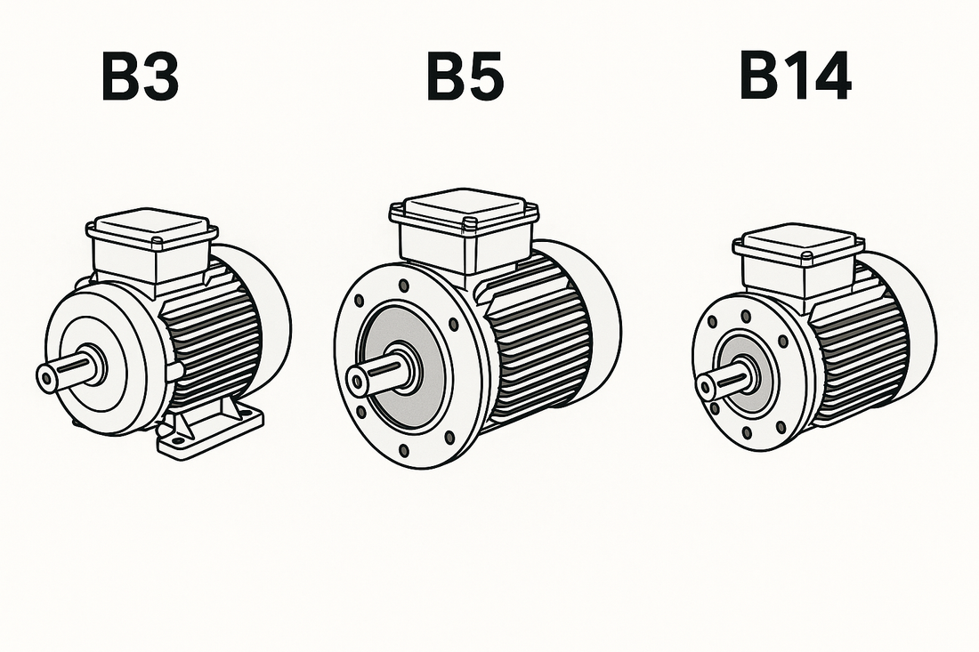
⚙️ 1. Form B3 – Motor with feet (without flange)
-
Description : The motor is equipped with feet for fixing to the base.
-
Assembly : On a horizontal surface using bolts in the feet.
-
Typical applications : Pumps, fans, conveyor belts.
🛠️ 2. Form B5 – Motor with large flange
-
Description : The motor has a large diameter front flange with through holes .
-
Assembly : Front fixing to the machine via bolts passing through the flange.
-
Typical applications : Gearboxes, machine tools, pumps.
🔩 3. Form B14 – Motor with small flange
-
Description : The motor has a small diameter front flange with threaded holes .
-
Assembly : Front fixing to the machine using screws that screw into the threaded holes of the flange.
-
Typical applications : Compact machines, small gearboxes, automation.
🔄 4. Combined forms: B35 and B34
-
B35 : Motor with feet and B5 flange . Offers flexibility for both base and front mounting.
-
B34 : Motor with feet and B14 flange . Ideal for compact applications requiring both mounting options.
Choosing the right flange is essential to ensure safe assembly and compliance with your application's specifications. If you have any questions or need assistance, don't hesitate to contact us: we're here to help you find the solution that best suits your needs.